Robot Final Report
MAE 3 Section A07
Colin Huang
Description of the Robot:
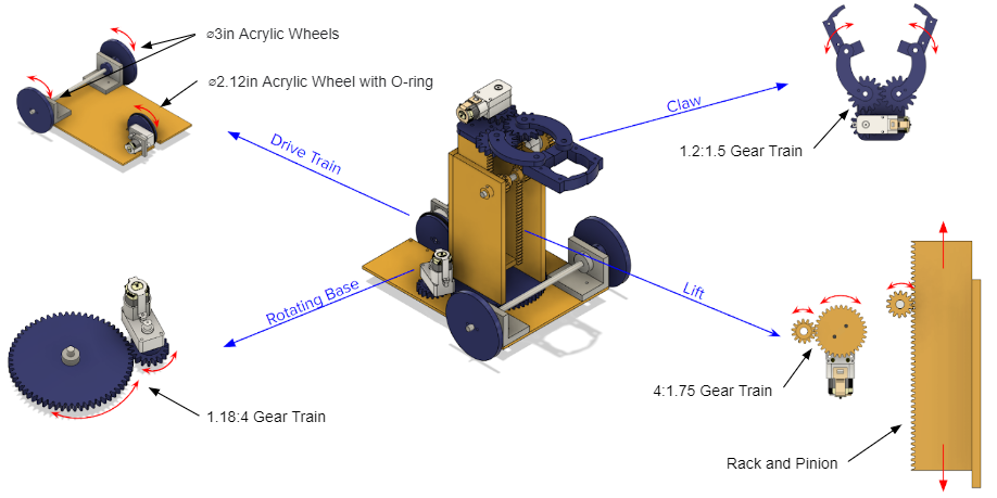
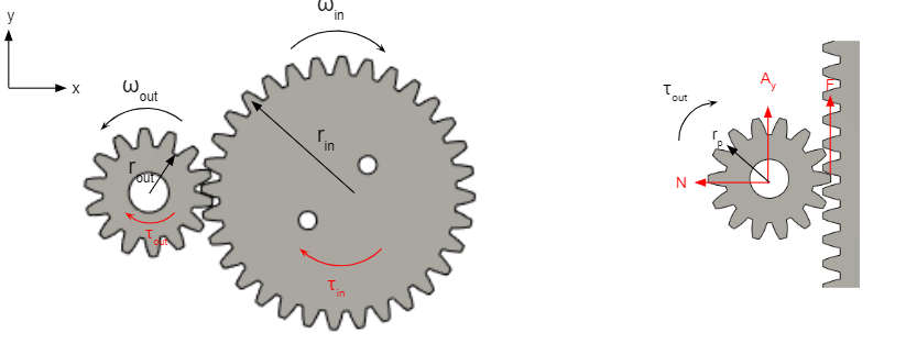
Figure 1: Four Powered Components of the Robot
All components utilize a geared motor. The rotating base rotates the lift and claw components with a 1.18:4 gear ratio. The drivetrain is a three-wheel drive, with one 2.12inch diameter and two 3 inch diameter wheels, powered by a single geared motor. The 2.12 inch diameter acrylic wheel is connected to an O-ring for greater traction. The claw uses a 1.2:1.5 gear ratio to grasp onto field elements. The analyzed component will be the lift mechanism. The lift uses a 4:1.75 gear ratio to rotate two pinion gears fixed onto an aluminum shaft. The rotation of the pinion gears moves the two attached rack elements up and down.
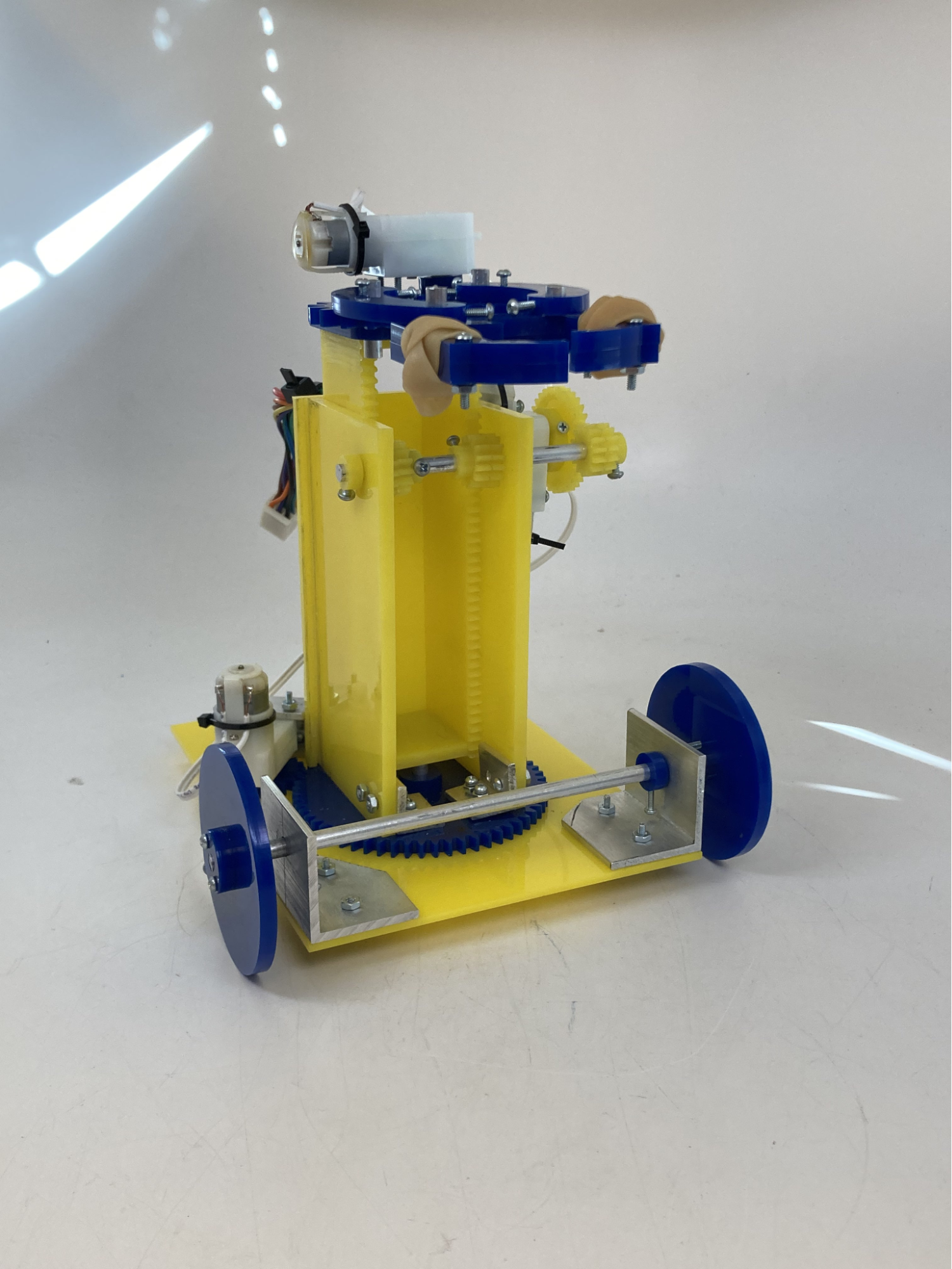
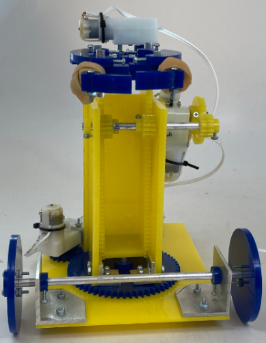
Figure 2: Completed Robot
Analyzed Component: Lift
Functional Requirements of the Lift Component:
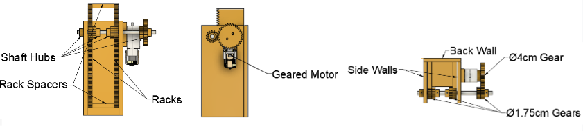
Figure 3: Annotated Perspectives of the Lift Component CAD
Functionality of the Lift Component:
The lift component performed as expected in regards to the maximum height reached, stability, and speed. Three trials were performed to test the height reached in 2 seconds. The measured heights of the three trials were 4.1 inches, 4.1 inches, and 4.0 inches. As a result, the average speed measured was a vertical speed of 2.03 inches per second. The speed of the lift mechanism is consistent with rack and pinion drives, which are known to provide high speeds due to the conversion of rotational speed to linear speed. Furthermore, the exterior gear train has a smaller output value than the input value, focusing on rotational speed rather than torque. Finer adjustments between 0.5 and 1 inch in the upward direction were possible. However, lowering the lift component was less precise and returned to the starting position within one second when attempting to lower the claw. This can be explained by the force applied by the motor compounded by the force of gravity. Although the motor is no longer in the process of turning, the shaft and claw components continue to move downward due to momentum. On its way down, there is a downward force between the rack and pinion to apply torque on the pinion gears all the way to the exterior input gear. The exterior gear train flips its ratio to 1.75:4, resulting in the motor shaft experiencing sufficient torque to turn as well. Overall, with the lift component, reaching the first and second floor of Geisel was possible, allowing the robot to score up to three points by dropping the sun and speaker elements on level 1 and the speaker element on level 2.
Analysis of Lift Component:
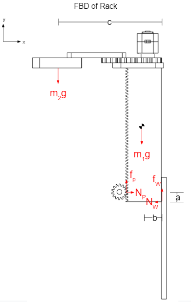
The maximum amount of mass that can be placed at the lift component’s maximum height before jamming will be the focus of this examination of the lift component. The analysis will first analyze the rack element at its full height with the pinion gears, the analysis will only consider a single gear, and the back wall serving as the bearings. The second part of the analysis will determine if the rack is jammed. The moment created by the claw will not be included. Thus, this assumption will be optimistic. The center of mass with the claw’s additional weight will also be considered. A conservative assumption included in this analysis is that friction caused by the two side walls will be ignored. The static coefficient of friction of acrylic on acrylic will be assumed to be at maximum at 0.2.
Figure 4: FBD of Stationary Rack at Maximum Height
Analysis of Stationary Rack at Maximum Height:


 *
*
*Predicted weight from Fusion 360 including nuts and bolts


Measured Maximum Mass Through Experimentation: 142 g
Figure 5: Power Analysis of Gear Train and FBD of Pinion Gear
Analysis of Pinion Gear:


Power In: 
Power Out: 


Factor of Safety:
Mass of Speaker Element: 34 g
Measured Maximum Mass: 142 g

The factor of safety of 4.2 means that the bearings of the lift mechanism provide more than sufficient stability for the claw to be able to hold onto blocks. Increasing the width of the pinion gears to provide more stability to resist the moment of a heavy load on the claw can increase performance.
Conclusion:
The force analysis of the mass estimated the maximum mass that the lift component could support to be 0.154 kg. Experimentation through the use of a plastic bag filled with nuts and bolts hooked onto the claw through the use of a paperclip and testing if the motor could lower the shaft found the actual maximum mass to be 142 kg. Thus, the error can be calculated using the percent error formula, producing a percentage of 7.79%. The error can be attributed to the assumption regarding the moment created by the claw and other additional small masses that were not considered. Another reason is the unknown coefficient of friction between acrylic and acrylic. The value of 0.2 was obtained from a Material Contact Properties Table on the internet (http://atc.sjf.stuba.sk/files/mechanika_vms_ADAMS/Contact_Table.pdf). This may have resulted in the error found in the analysis of the pinion gear, which should be not experiencing a moment. However, the error is relatively small and thus can be considered consistent with the accuracy of the maximum mass found in the rack analysis.
The major limitation of the lift design was the height limitation. The base of the robot ended up to be lower than I had anticipated and I had allotted 2 inches toward the base of the robot to fit the height constraint. However, the reduction in height reduced the maximum height from down to 12.7 inches from 14.7 inches. If given the opportunity to repeat the competition, I would revise the gear ratio of the exterior gear train of the lift system. The current sizes of the gear train and pinion gears were also chosen due to the physical space they took up. Larger pinion gears would mean that the side walls of the lift would have to be significantly longer. A gear ratio that balanced speed and torque while not taking an absurd amount of space would have been ideal. Furthermore, adding delrin to direct the rack on the inside of the side walls to make the vertical motion smoother or redesigning the rack to stop at the maximum height would have benefitted my team in controlling the robot. For the overall robot, I would have opted for the traditional four-wheel robot with two geared motors for greater stability and reliability. The claw could have also had greater reach, as our robot often struggled with grasping for field elements after pushing them out of reach. The biggest technical lesson I gained from this project was to learn how to balance trusting your instincts and slowing down to consider all facets of a situation or issue. There were many times when my teammates and I felt that a certain direction or design was very intuitive and reliable and that intuition paid off. Other times, rushing to solve an issue with multiple fixes exacerbated the issue and required taking a step back to reconsider. Overall, working hard, communication with one’s teammates, and attention to detail will always produce results.
Design Process:
Given that the robot needed to be built and completed within 6 weeks, prioritization and scheduling was exceedingly important in my team’s design process. Early on, during the first risk reduction phase, my team prioritized the lift component. While performing the risk reduction on the rack and pinion was necessary as it is a vital part of the robot, it also left my team less time to refine their own designs. The rack and pinion proved to be a reliable component that functioned with little difficulty in comparison to other components in our design. The claw and rotating base were fabricated and functional within a short amount of time; however, the drive train would have benefited from earlier consideration. The design for the wheel attached to the motor went through several iterations and changed from a non-geared motor to a geared motor, leading to a functional, yet not ideal, design. Rather than splitting off to complete the three other components at once, prioritizing one or two components after risk reducing and assembling the lift component would have been a better approach. Despite these complications, following the Gantt chart and working towards at least 2 deliverables a week helped my team pull through. Assigning roles through the Gantt chart ensured that all team members were productive during their time in the design studio. The chart also helped my team set an order of magnitude in regards to what needed to be completed within the week. This organization helped us designate how many team members to allot for a task and what tasks should be completed first. Beyond the Gantt chart and outside of design studio hours, consistently writing out in detail what needs to be done in our group chat was also important in maximizing the time we had in the design studio. In the group chat, we would organize roles down to the fabrication of individual parts (e.g. cutting and drilling L-brackets or preparing a file for the Lasercamm) to ensure that no time is being wasted. Overall, despite the numerous complications my team faced over the course of these 6 weeks, regular prioritization and scheduling of tasks was vital in completing the project.